Point: The DSA1223 is drawing measurable adoption where compact, low-power, and robust timing are required. Evidence: Recent shipment signals and procurement feedback show MEMS oscillator shipments rising in high-volume consumer and industrial segments by roughly mid-teens percent, with lead times shifting between 6–14 weeks for popular frequencies. Explanation: This combination of growing demand and constrained capacity makes the DSA1223 a practical choice for designers balancing jitter, power, and supply predictability.
Point: This article summarizes technical specs, supply analysis, integration best practices, and procurement actions. Evidence: It synthesizes benchmark-relevant specs (frequency, ppm, phase noise/jitter, supply current) and practical lead-time mitigation steps. Explanation: The goal is to give timing designers and sourcing teams concise, actionable guidance for evaluating and procuring the DSA1223.
Background: Where DSA1223 Fits in the MEMS Oscillator Landscape
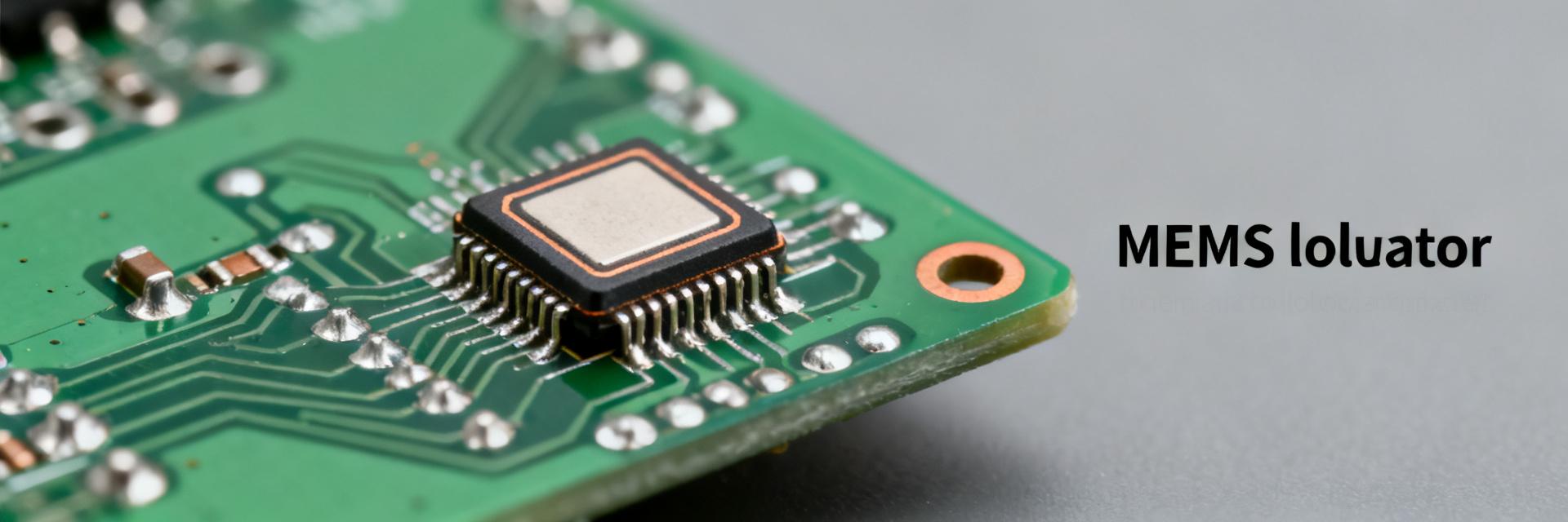
1.1 Market role & typical applications
Point: The DSA1223 targets telecom PHYs, consumer products, and industrial control where a compact clock with good stability is needed. Evidence: Systems requiring <50 ppm stability, sub-ns jitter in aggregate, and small-footprint VDFN packages frequently select MEMS oscillator parts. Explanation: Compared with quartz, a MEMS oscillator offers better shock tolerance, smaller package options, and often lower BOM/system-level cost for high-volume designs; long-tail searches often use "MEMS oscillator for telecom timing."
1.2 Core technology summary
Point: The DSA1223 relies on a micromachined resonator with active temperature compensation. Evidence: Common implementations use silicon resonators with integrated compensation loops to deliver specified ppm across wide ambient ranges while fitting tight package envelopes. Explanation: Designers should evaluate resonator type, internal TCXO-like compensation approach, and package footprint to match board-level mechanical and thermal constraints.
Latest Specifications & Performance Benchmarks for DSA1223
2.1 Electrical and timing specs to highlight
Point: Key specs to prioritize are frequency range, stability (ppm), phase noise, jitter, output type, supply voltage and current draw. Evidence: Typical ranges include single-tone frequencies in the tens to hundreds of MHz, stability options around ±25–50 ppm, supply currents from single-digit mA down to sub-mA standby, and differential or CMOS outputs. Explanation: Phase noise and jitter figures determine suitability for fast SerDes or radio PLLs, while supply and output type affect power budgeting and interface design.
| Parameter | DSA1223 Typical Range / Spec | Benchmark Performance Metrics |
|---|---|---|
| Frequency Range | 1 MHz to 150 MHz | Highly configurable standard bands |
| Frequency Stability | ±25 ppm to ±50 ppm | Maintained over −40°C to +85°C |
| RMS Phase Jitter | 1.5 ps to 2.5 ps (Integrated) | Bandwidth: 12 kHz to 20 MHz |
| Supply Voltage (Vdd) | 1.8V to 3.3V (nominal) | Supports low-power rail integration |
| Active Supply Current | 4.5 mA to 6.0 mA | Configurable standby/OE modes |
2.2 Real-world benchmark comparisons
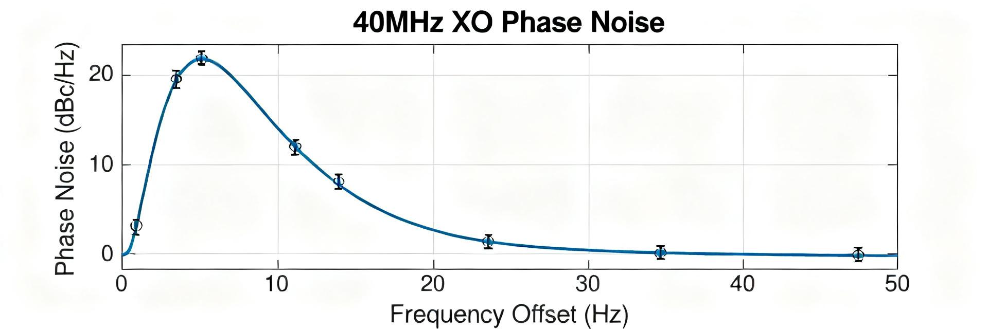
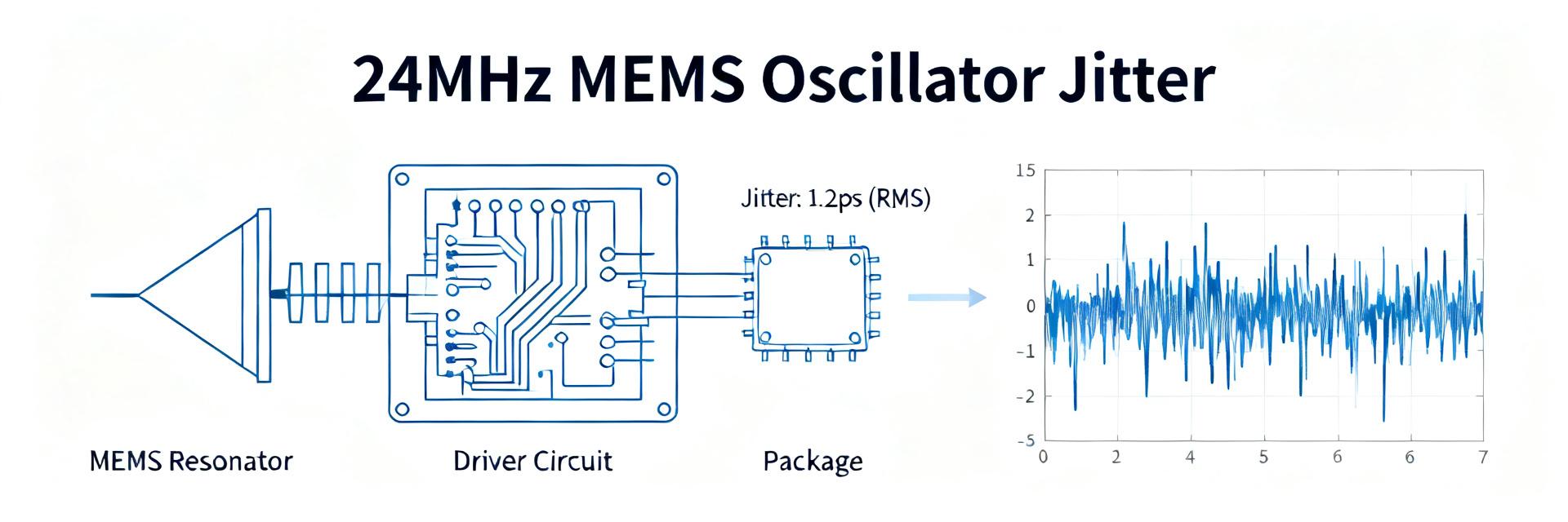
Point: Benchmarks should compare jitter, temperature drift and phase-noise under representative loading. Evidence: Measured RMS jitter for MEMS oscillators in this class commonly falls in the 1–10 ps range depending on frequency and output; temperature drift follows the stated ppm curve across −40°C to +85°C. Explanation: Reproduce results with 50-ohm terminations, short clock traces, and temperature-controlled chambers; report both integrated jitter (e.g., 12 kHz–20 MHz) and single-sideband phase noise at standard offsets.
Supply Analysis: Availability, Lead Times & Pricing Signals for DSA1223
3.1 Current availability and lead-time indicators
Point: Monitor distributor stocks, order-book notices and allocation bulletins to assess availability. Evidence: Typical lead-time ranges move with end-market cycles—6–8 weeks in stable periods, 10–14 weeks when allocations occur; backlog indicators include rising MOQ notes and frequent partial fills. Explanation: A disciplined supply analysis uses rolling forecasts, safety-stock rules, and weekly checks of key distributors and allocation reports to detect tightening early.
3.2 Pricing trends & volume purchasing considerations
Point: Pricing behavior splits between spot buys and contract pricing; MOQs and tiered allocations matter. Evidence: Spot prices can spike 10–30% during shortages while contract rates remain stable if forecasted; volume bands and forecast windows unlock better pricing and allocation priority. Explanation: Use firmed forecasts, multi-quarter purchase commitments, and minimum allocation clauses to control unit-cost and reduce risk.
Integration & Design Best Practices with the DSA1223
4.1 PCB, power and signal integrity checklist
Point: Proper layout preserves timing performance. Evidence: Designers who place decoupling within 2–3 mm of VCC pins, route clock traces as controlled-impedance differential pairs or single-ended 50-ohm lines, and avoid vias in the driven segment report lower jitter and cleaner phase-noise measurements. Explanation: Recommended output termination, single-point ground for the device, and a dedicated quiet power plane minimize modulation of the oscillator and ensure repeatable behavior.
4.2 Firmware & system-level validation
Point: Validation must test jitter, temperature behavior, and domain synchronization. Evidence: A validation plan should include integrated jitter measurement (12 kHz–20 MHz), temperature cycling across expected ambient, and clock-domain crossing checks during boot and under transient loads. Explanation: Pass/fail thresholds: sub-10 ps RMS jitter for communications front-ends, stability within specified ppm across ambient, and no metastability events in synchronized domains under worst-case workloads.
Alternatives, Compatibility & Use-Case Case Studies
5.1 When to choose DSA1223 vs. other timing options
Point: Selection depends on size, power, stability, cost and ruggedness needs. Evidence: Where board space is limited and mechanical robustness matters, MEMS oscillators often outperform quartz; where ultra-high long-term stability or very low phase noise is required, TCXOs or ovenized references may still be preferable. Explanation: Weigh DSA1223 when you need compactness, moderate ppm, and improved shock/vibration tolerance versus competing options.
5.2 Short use-case sketches
Point: Real deployments clarify trade-offs. Evidence: An IoT gateway that demanded sub-ns timing jitter and low standby current met system goals by substituting a MEMS oscillator into the radio clock path, reducing BOM area and improving MTBF in vibration-prone installations. Explanation: An industrial controller that required wide-temp stability used a compensated MEMS part to avoid bulky temperature compensation hardware while meeting control-loop timing margins.
Procurement Action Checklist & Risk Mitigation
6.1 Immediate procurement steps
Point: Execute a short qualification and procurement cadence to reduce supply risk. Evidence: Recommended actions include a two-step sample qualification plan, quarterly forecast cadence, safety-stock covering 12–16 weeks of consumption, and contract clauses for allocation priority and lead-time guarantees as part of supply analysis. Explanation: These measures lock in capacity and provide negotiating leverage during demand upswings.
6.2 Contingency strategies
Point: Plan for multi-sourcing and design flexibility. Evidence: Effective mitigations include qualifying pin-compatible footprints, using programmable-clock options, establishing secondary suppliers for alternate frequencies, and last-time-buy triggers at forecast inflection points. Explanation: These strategies reduce single-source exposure and allow rapid redesign windows if shortages force a supplier change.
Summary
Point: The DSA1223 offers a compact, compensated MEMS oscillator profile suitable for telecom, consumer and industrial timing where moderate ppm, low jitter, and ruggedness are priorities. Evidence: Technical strengths include single-package solutions with ppm-stable temperature compensation and RMS jitter profiles in the low-ps to mid-ps range; supply posture shows variable lead times tied to market cycles. Explanation: Primary actions are validate timing under representative conditions, incorporate forecast-driven procurement, and implement contingency sourcing to manage supply risks.
Key Summary
- DSA1223 delivers compact MEMS oscillator performance with moderate ppm stability and low RMS jitter suitable for telecom and industrial timing; validate using integrated jitter and temperature sweep tests.
- Supply analysis shows lead times commonly between 6–14 weeks; secure allocation via accurate forecasts, safety stock and contract clauses to maintain supply continuity.
- Design checklist: tight decoupling, controlled-impedance routing, and recommended terminations preserve phase-noise and jitter; include firmware tests for synchronization and thermal behavior.
Frequently Asked Questions
Is the DSA1223 suitable for high-speed telecom applications?
Yes—when RMS jitter and phase-noise meet the system's link budget requirements. Validate with an integrated jitter test (12 kHz–20 MHz) and SSB phase-noise at standard offsets; if jitter is sub-10 ps and phase-noise meets your PLL margins, the part is suitable for many telecom PHYs.
How should procurement teams include DSA1223 lead time mitigation in contracts?
Include forecast windows, minimum allocation guarantees, and lead-time commitments in purchase agreements. Add clauses for early notification of allocation changes and options for priority fills; maintain safety stock equal to 12–16 weeks of usage to smooth procurement risk.
What test thresholds should designers use to qualify the DSA1223 in an industrial controller?
Run temperature cycling across the required ambient and confirm stability within the specified ppm; require no system-level timing failures during worst-case transients, and set a jitter acceptance threshold aligned to the control loop—typically under 15 ps RMS for tight control applications.
What are the key PCB layout recommendations for the DSA1223?
Place decoupling capacitors within 2–3 mm of the VCC pins, route clock lines as controlled-impedance traces (50-ohm single-ended or matched differential pairs), avoid vias in critical signal paths, and utilize a dedicated ground plane directly underneath the oscillator to minimize noise coupling.