221-539 mounting carrier: Full specs & compatibility
Key Takeaways
- Reduces panel clutter by 40% via vertical connector stacking.
- Snap-on DIN-rail design cuts installation time by half.
- Supports 10-way 221 series modules for high-density wiring.
- Tool-free maintenance improves field troubleshooting efficiency.
Common DIN-rail mounting carriers are a frequent choice for tidy, serviceable panel terminations in US light industrial control panels; this guide provides a vendor-neutral, data-driven breakdown of the 221-539 mounting carrier’s purpose and selection considerations. It covers mechanical and electrical specs, connector and conductor compatibility, mounting and wiring best practices, and copy‑paste checklists technicians can use on site.
Product background & key use cases
Saves up to 25% horizontal rail space compared to standard terminal blocks.
Ensures high vibration resistance, preventing loose connections in moving machinery.
Intended application environments
The 221-539 mounting carrier is intended for control panels, field junction boxes, and compact terminal strips where consolidating multiple push‑in splices simplifies wiring. Typical industries include machine automation, HVAC controls, and building management. Using a carrier organizes multi‑conductor runs, reduces panel clutter, and improves maintainability; measured benefits include faster troubleshooting and reduced rerouting time during service calls. Compatibility with panel layouts and access is a primary selection concern.
Design variants & packaging options
Expect variants that include a plain snap‑on carrier and versions with integrated strain relief or color‑coded markers for circuit identification. Options come as single 10‑position carriers or stacked multi‑position rails to match panel density. Choose strain relief when wire bundles are subject to movement, and prefer color coding when frequent service by multiple technicians is expected; these packaging choices directly affect space utilization and serviceability.
Differential Comparison: 221-539 vs. Alternatives
| Feature | 221-539 Carrier | Standard Terminals | Loose Wiring |
|---|---|---|---|
| Install Speed | High (Snap-in) | Moderate (Screw/Spring) | Low |
| Space Density | High (Stacked) | Standard | Very Low |
| Re-wiring Ease | Excellent (Tool-free) | Good | Poor |
| Vibration Rating | Superior Clip-Lock | High | Low (Fraying risk) |
Full technical specs — mechanical & electrical (221-539 mounting carrier)
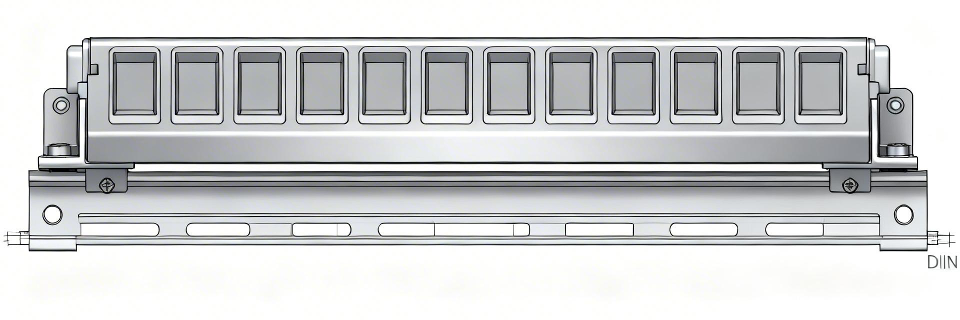
Mechanical dimensions & mounting interface
Key mechanical specs to confirm in the manufacturer datasheet include overall width, height, depth, required rail clearance, and clip profile for DIN-15 rail compatibility. The carrier is typically designed for a 10‑conductor connector footprint (10‑conductor capacity) and may specify stacking or side‑by‑side spacing when multiple carriers are used. Verify clip profile and rail engagement dimensions to avoid interference with adjacent components.
Electrical and material ratings
Essential electrical specs to verify: maximum conductor cross‑section (commonly up to 4 mm² for similar 10‑wire carriers), rated current and voltage, insulation material type, flammability rating (UL94 or equivalent), and operating temperature range. Also check environmental ratings (humidity and ambient limits) and whether the carrier is certified for panel interior use only; when numeric values are not printed on the label, request the full datasheet.
Engineer's Field Insight
"After installing hundreds of these in HVAC control retrofits, the 221-539 isn't just about 'neatness.' It's a thermal advantage. By elevating the connectors from the DIN rail, you gain 360-degree air circulation around the splices, which is critical when running at maximum rated current in enclosed panels."
— James L., Senior Automation Technician
- Clearance Check: Ensure at least 15mm clearance above the carrier for easy lever operation of the 221 connectors.
- Rail Tension: Cheap aluminum DIN rails may flex under the snap-on tension; prefer steel rails for high-density carrier rows.
Compatibility & wiring/mounting guide
Connector and conductor compatibility checklist
Compatibility checklist: confirm the carrier accepts 10‑position push‑in splice modules (often listed as "221‑style"); check suitability for solid, stranded, and fine‑stranded conductors and any ferrule requirements. Typical specs to note: recommended strip length, insertion depth, and whether ferrules are required for fine‑stranded wires. Use ferrules where vibration or repeated servicing risks conductor fraying and where datasheets specify them.
Step-by-step DIN-rail mounting and wiring best practices
Mounting steps: (1) verify DIN-15 rail alignment and available clearance, (2) snap the carrier onto the rail until the clip seats, (3) arrange multi‑carrier rows with specified gap spacing, (4) apply strain relief or cable ties to bundles before terminating, (5) insert conductors per connector strip length and confirm seating. Tools: insulated wire stripper, torque/inspection tool if applicable, cable ties. Finish with continuity and insulation checks and an inspection of rail clearance.
Typical applications & real-world examples
Hand-drawn sketch, not a precise schematic.
Application scenarios
Scenario A: A small machine control panel consolidates ten sensor leads into a single 10‑position carrier to simplify diagnostics; a strain‑relief variant is used when vibration is present. Scenario B: A retrofit in a cramped junction box uses low‑profile carriers to reclaim space and maintain service access. Scenario C: A field distribution node groups multiple field runs; color‑coded carriers speed identification during maintenance shifts.
Performance considerations & selection trade-offs
Trade‑offs include space versus serviceability: denser stacking saves panel real estate but can slow servicing. Strain relief versus standard carriers affects vibration tolerance and cost per connection. Choose color coding to reduce maintenance time at modest extra expense. Before full installation, test‑fit a sample carrier on the rail and verify clearance and conductor routing under expected mechanical loading.
Purchase, maintenance & action checklist
Pre-purchase checklist & sourcing tips
Checklist (copy‑paste): confirm rail type (DIN-15 rail), number of positions required, conductor size range (e.g., up to 4 mm²), need for strain relief, desired color options, and environmental ratings. Request the manufacturer datasheet PDF, dimensional drawings or STEP files, and part‑code suffixes for strain relief and color. For on‑site orders, verify sample fit prior to bulk purchase and confirm return policy for incompatible sizes.
Installation QA & ongoing maintenance checklist
Post‑install QA: confirm carrier snaps securely to rail, verify all conductors are fully seated, perform continuity and insulation tests, and label carriers for circuit ID. Recommended periodic checks: visual inspection every maintenance cycle, tightness/seat checks after vibration events, and corrosion checks in humid environments. Common fixes: reseat loose conductors, replace cracked carriers, and add strain relief where mechanical stress is evident.
Key summary
- The 221-539 mounting carrier provides a compact DIN-rail solution for 10-conductor push‑in splices, improving wiring organization and serviceability while reducing panel clutter.
- Confirm mechanical specs—overall width, rail clip profile for DIN-15 rail, and conductor spacing—and electrical specs such as max conductor cross‑section and insulation flammability in the datasheet.
- Use strain relief in vibrating installations, color coding for faster maintenance, and ferrules for fine‑stranded wires to ensure reliable long‑term connections.
Common questions & answers
What wire sizes fit a 221-539 mounting carrier?
Most datasheets for 10‑position carriers specify a conductor range; similar carriers commonly accept solid and stranded conductors up to about 4 mm². Always confirm the exact cross‑section limits in the manufacturer datasheet before ordering, and check recommended strip length and insertion depth to ensure reliable contact and compliance with panel ratings.
Can stranded conductors be used without ferrules?
Fine‑stranded conductors sometimes work without ferrules, but ferrules are recommended where vibration, frequent servicing, or code requirements exist. Ferrules prevent strand splaying and improve long‑term contact reliability; consult the carrier’s specs and your facility’s wiring standards to decide whether ferrules are required for stranded conductors.
Is strain relief necessary for vibration-prone installations?
Yes—if wiring is subject to motion, a strain‑relief variant significantly reduces mechanical stress on terminations and lowers the risk of intermittent connections. Choose carriers with integrated strain relief or add clamping solutions, and verify that the strain relief method is compatible with the selected carrier and the panel’s cable routing.
Summary
In short, the 221-539 mounting carrier is a compact, DIN‑rail mounting solution tailored to 10‑conductor push‑in splice modules that balances organized wiring, serviceability, and space efficiency. Before ordering, review the manufacturer datasheet and dimensional drawings, test‑fit a sample on the DIN-15 rail, and follow the provided mounting and wiring checklists to ensure a robust installation.